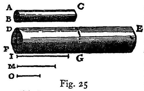
Given a cylinder or prism of the greatest length consistent with its not breaking under its own weight; and having given a greater length, to find the diameter of another cylinder or prism of this greater length which shall be the only and largest one capable of withstanding its own weight.
Let BC be the largest cylinder capable of sustaining its own weight; and let DE be a length greater than AC: the problem is to find the diameter of the cylinder which, having the length DE, shall be the largest one just able to withstand its own weight. Let I be a third proportional to the lengths DE and AC; let the diameter FD be to the diameter BA as DE is to I; draw the cylinder FE; then, among all cylinders having the same proportions, this is the largest and only one just capable of sustaining its own weight.
Let M be a third proportional to DE and I: also let O be a fourth proportional to DE, I, and M; lay off FG equal to AC. Now since the diameter FD is to the diameter AB as the length DE is to I, and since O is a fourth proportional to DE, I and M, it follows that FDmacronsup3:BAmacronsup3=DE:O. But the resistance [bending strength] of the cylinder DG is to the resistance of the cylinder BC as the cube of FD is to the cube of BA: hence the resistance of the cylinder DG is to that of cylinder BC as the length DE is to O. And since the moment of the cylinder BC is held in equilibrium by [è equale alla] its resistance, we shall accomplish our end (which is to prove that the moment of the cylinder FE is equal to the resistance located at FD), if we show that the moment of the cylinder FE is to the moment of the cylinder BC as the resistance DF is to the resistance BA, that is, as the cube of FD is to the cube of BA, or as the length DE is to O. The moment of the cylinder FE is to the moment of the cylinder DG as the square of DE is to the square of AC, that is, as the length DE is to I; but the moment of the cylinder DG is to the moment of the cylinder BC, as the square of DF is to the square of BA, that is, as the square of DE is to the square of I, or as the square of I is to the square of M, or, as I is to O. Therefore by equating ratios, it results that the moment of the cylinder FE is to the moment of the cylinder BC as the length DE is to O, that is, as the cube of DF is to the cube of BA, or as the resistance of the base DF is to the resistance of the base BA; which was to be proven.
This demonstration, Salviati, is rather long and difficult to keep in mind from a single hearing. Will you not, therefore, be good enough to repeat it?
As you like; but I would suggest instead a more direct and a shorter proof: this will, however, necessitate a different figure.
The favor will be that much greater: nevertheless I hope you will oblige me by putting into written form the argument just given so that I may study it at my leisure.
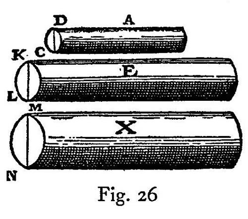
I shall gladly do so. Let A denote a cylinder of diameter DC and the largest capable of sustaining its own weight: the problem is to determine a larger cylinder which shall be at once the maximum and the unique one capable of sustaining its own weight.
Let E be such a cylinder, similar to A, having the assigned length, and having a diameter KL. Let MN be a third proportional to the two lengths DC and KL: let MN also be the diameter of another cylinder, X, having the same length as E: then, I say, X is the cylinder sought. Now since the resistance of the base DC is to the resistance of the base KL as the square of DC is to the square of KL, that is, as the square of KL is to the square of MN, or, as the cylinder E is to the cylinder X, that is, as the moment E is to the moment X; and since also the resistance [bending strength] of the base KL is to the resistance of the base MN as the cube of KL is to the cube of MN, that is, as the cube of DC is to the cube of KL, or, as the cylinder A is to the cylinder E, that is, as the moment of A is to the moment of E; hence it follows, ex æquali in proportione perturbata, that the moment of A is to the moment of X as the resistance of the base DC is to the resistance of the base MN; therefore moment and resistance are related to each other in prism X precisely as they are in prism A.
Let us now generalize the problem; then it will read as follows:
Given a cylinder AC in which moment and resistance [bending strength] are related in any manner whatsoever; let DE be the length of another cylinder; then determine what its thickness must be in order that the relation between its moment and resistance shall be identical with that of the cylinder AC.
Using Fig. 25 in the same manner as above, we may say that, since the moment of the cylinder FE is to the moment of the portion DG as the square of ED is to the square of FG, that is, as the length DE is to I; and since the moment of the cylinder FG is to the moment of the cylinder AC as the square of FD is to the square of AB, or, as the square of ED is to the square of I, or, as the square of I is to the square of M, that is, as the length I is to O; it follows, ex æquali, that the moment of the cylinder FE is to the moment of the cylinder AC as the length DE is to O, that is, as the cube of DE is to the cube of I, or, as the cube of FD is to the cube of AB, that is, as the resistance of the base FD is to the resistance of the base AB; which was to be proven.
From what has already been demonstrated, you can plainly see the impossibility of increasing the size of structures to vast dimensions either in art or in nature; likewise the impossibility of building ships, palaces, or temples of enormous size in such a way that their oars, yards, beams, iron-bolts, and, in short, all their other parts will hold together; nor can nature produce trees of extraordinary size because the branches would break down under their own weight; so also it would be impossible to build up the bony structures of men, horses, or other animals so as to hold together and perform their normal functions if these animals were to be increased enormously in height; for this increase in height can be accomplished only by employing a material which is harder and stronger than usual, or by enlarging the size of the bones, thus changing their shape until the form and appearance of the animals suggest a monstrosity. This is perhaps what our wise Poet had in mind, when he says, in describing a huge giant:
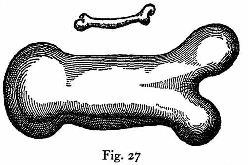
To illustrate briefly, I have sketched a bone whose natural length has been increased three times and whose thickness has been multiplied until, for a correspondingly large animal, it would perform the same function which the small bone performs for its small animal. From the figures here shown you can see how out of proportion the enlarged bone appears. Clearly then if one wishes to maintain in a great giant the same proportion of limb as that found in an ordinary man he must either find a harder and stronger material for making the bones, or he must admit a diminution of strength in comparison with men of medium stature; for if his height be increased inordinately he will fall and be crushed under his own weight. Whereas, if the size of a body be diminished, the strength of that body is not diminished in the same proportion; indeed the smaller the body the greater its relative strength. Thus a small dog could probably carry on his back two or three dogs of his own size; but I believe that a horse could not carry even one of his own size.
This may be so; but I am led to doubt it on account of the enormous size reached by certain fish, such as the whale which, I understand, is ten times as large as an elephant; yet they all support themselves.
Your question, Simplicio, suggests another principle, one which had hitherto escaped my attention and which enables giants and other animals of vast size to support themselves and to move about as well as smaller animals do. This result may be secured either by increasing the strength of the bones and other parts intended to carry not only their weight but also the superincumbent load; or, keeping the proportions of the bony structure constant, the skeleton will hold together in the same manner or even more easily, provided one diminishes, in the proper proportion, the weight of the bony material, of the flesh, and of anything else which the skeleton has to carry. It is this second principle which is employed by nature in the structure of fish, making their bones and muscles not merely light but entirely devoid of weight.
The trend of your argument, Salviati, is evident. Since fish live in water which on account of its density [corpulenza] or, as others would say, heaviness [gravità] diminishes the weight [peso] of bodies immersed in it, you mean to say that, for this reason, the bodies of fish will be devoid of weight and will be supported without injury to their bones. But this is not all; for although the remainder of the body of the fish may be without weight, there can be no question but that their bones have weight. Take the case of a whale’s rib, having the dimensions of a beam; who can deny its great weight or its tendency to go to the bottom when placed in water? One would, therefore, hardly expect these great masses to sustain themselves.
A very shrewd objection! And now, in reply, tell me whether you have ever seen fish stand motionless at will under water, neither descending to the bottom nor rising to the top, without the exertion of force by swimming?
This is a well-known phenomenon.
The fact then that fish are able to remain motionless under water is a conclusive reason for thinking that the material of their bodies has the same specific gravity as that of water; accordingly, if in their make-up there are certain parts which are heavier than water there must be others which are lighter, for otherwise they would not produce equilibrium.
Hence, if the bones are heavier, it is necessary that the muscles or other constituents of the body should be lighter in order that their buoyancy may counterbalance the weight of the bones. In aquatic animals therefore circumstances are just reversed from what they are with land animals inasmuch as, in the latter, the bones sustain not only their own weight but also that of the flesh, while in the former it is the flesh which supports not only its own weight but also that of the bones. We must therefore cease to wonder why these enormously large animals inhabit the water rather than the land, that is to say, the air.
I am convinced and I only wish to add that what we call land animals ought really to be called air animals, seeing that they live in the air, are surrounded by air, and breathe air.
I have enjoyed Simplicio’s discussion including both the question raised and its answer. Moreover I can easily understand that one of these giant fish, if pulled ashore, would not perhaps sustain itself for any great length of time, but would be crushed under its own mass as soon as the connections between the bones gave way.
I am inclined to your opinion; and, indeed, I almost think that the same thing would happen in the case of a very big ship which floats on the sea without going to pieces under its load of merchandise and armament, but which on dry land and in air would probably fall apart. But let us proceed and show how:
Given a prism or cylinder, also its own weight and the maximum load which it can carry, it is then possible to find a maximum length beyond which the cylinder cannot be prolonged without breaking under its own weight.
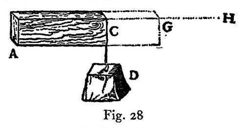
Let AC indicate both the prism and its own weight; also let D represent the maximum load which the prism can carry at the end C without fracture; it is required to find the maximum to which the length of the said prism can be increased without breaking. Draw AH of such a length that the weight of the prism AC is to the sum of AC and twice the weight D as the length CA is to AH; and let AG be a mean proportional between CA and AH; then, I say, AG is the length sought. Since the moment of the weight [momento gravante] D attached at the point C is equal to the moment of a weight twice as large as D placed at the middle point AC, through which the weight of the prism AC acts, it follows that the moment of the resistance of the prism AC located at A is equivalent to twice the weight D plus the weight of AC, both acting through the middle point of AC. And since we have agreed that the moment of the weights thus located, namely, twice D plus AC, bears to the moment of AC the same ratio which the length HA bears to CA and since AG is a mean proportional between these two lengths, it follows that the moment of twice D plus AC is to the moment of AC as the square of GA is to the square of CA. But the moment arising from the weight [momento premente] of the prism GA is to the moment of AC as the square of GA is to the square of CA; thence AG is the maximum length sought, that is, the length up to which the prism AC may be prolonged and still support itself, but beyond which it will break.
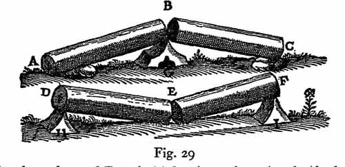
Hitherto we have considered the moments and resistances of prisms and solid cylinders fixed at one end with a weight applied at the other end; three cases were discussed, namely, that in which the applied force was the only one acting, that in which the weight of the prism itself is also taken into consideration, and that in which the weight of the prism alone is taken into consideration. Let us now consider these same prisms and cylinders when supported at both ends or at a single point placed somewhere between the ends. In the first place, I remark that a cylinder carrying only its own weight and having the maximum length, beyond which it will break, will, when supported either in the middle or at both ends, have twice the length of one which is mortised into a wall and supported only at one end. This is very evident because, if we denote the cylinder by ABC and if we assume that one-half of it, AB, is the greatest possible length capable of supporting its own weight with one end fixed at B, then, for the same reason, if the cylinder is carried on the point G, the first half will be counterbalanced by the other half BC. So also in the case of the cylinder DEF, if its length be such that it will support only one-half this length when the end D is held fixed, or the other half when the end F is fixed, then it is evident that when supports, such as H and I, are placed under the ends D and F respectively the moment of any additional force or weight placed at E will produce fracture at this point.
A more intricate and difficult problem is the following: neglect the weight of a solid such as the preceding and find whether the same force or weight which produces fracture when applied at the middle of a cylinder, supported at both ends, will also break the cylinder when applied at some other point nearer one end than the other.
Thus, for example, if one wished to break a stick by holding it with one hand at each end and applying his knee at the middle, would the same force be required to break it in the same manner if the knee were applied, not at the middle, but at some point nearer to one end?
This problem, I believe, has been touched upon by Aristotle in his Questions in Mechanics.
His inquiry however is not quite the same; for he seeks merely to discover why it is that a stick may be more easily broken by taking hold, one hand at each end of the stick, that is, far removed from the knee, than if the hands were closer together. He gives a general explanation, referring it to the lengthened lever arms which are secured by placing the hands at the ends of the stick. Our inquiry calls for something more: what we want to know is whether, when the hands are retained at the ends of the stick, the same force is required to break it wherever the knee be placed.
At first glance this would appear to be so, because the two lever arms exert, in a certain way, the same moment, seeing that as one grows shorter the other grows correspondingly longer.
Now you see how readily one falls into error and what caution and circumspection are required to avoid it. What you have just said appears at first glance highly probable, but on closer examination it proves to be quite far from true; as will be seen from the fact that whether the knee—the fulcrum of the two levers—be placed in the middle or not makes such a difference that, if fracture is to be produced at any other point than the middle, the breaking force at the middle, even when multiplied four, ten, a hundred, or a thousand times would not suffice. To begin with we shall offer some general considerations and then pass to the determination of the ratio in which the breaking force must change in order to produce fracture at one point rather than another.
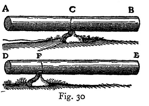
Let AB denote a wooden cylinder which is to be broken in the middle, over the supporting point C, and let DE represent an identical cylinder which is to be broken just over the supporting point F which is not in the middle. First of all it is clear that, since the distances AC and CB are equal, the forces applied at the extremities B and A must also be equal. Secondly since the distance DF is less than the distance AC the moment of any force acting at D is less than the moment of the same force at A, that is, applied at the distance CA; and the moments are less in the ratio of the length DF to AC; consequently it is necessary to increase the force [momento] at D in order to overcome, or even to balance, the resistance at F; but in comparison with the length AC the distance DF can be diminished indefinitely: in order therefore to counterbalance the resistance at F it will be necessary to increase indefinitely the force [forza] applied at D. On the other hand, in proportion as we increase the distance FE over that of CB, we must diminish the force at E in order to counterbalance the resistance at F; but the distance FE, measured in terms of CB, cannot be increased indefinitely by sliding the fulcrum F toward the end D; indeed, it cannot even be made double the length CB. Therefore the force required at E to balance the resistance at F will always be more than half that required at B. It is clear then that, as the fulcrum F approaches the end D, we must of necessity indefinitely increase the sum of the forces applied at E and D in order to balance, or overcome, the resistance at F.
What shall we say, Simplicio? Must we not confess that geometry is the most powerful of all instruments for sharpening the wit and training the mind to think correctly? Was not Plato perfectly right when he wished that his pupils should be first of all well grounded in mathematics? As for myself, I quite understood the property of the lever and how, by increasing or diminishing its length, one can increase or diminish the moment of force and of resistance; and yet, in the solution of the present problem I was not slightly, but greatly, deceived.
Indeed I begin to understand that while logic is an excellent guide in discourse, it does not, as regards stimulation to discovery, compare with the power of sharp distinction which belongs to geometry.
Logic, it appears to me, teaches us how to test the conclusiveness of any argument or demonstration already discovered and completed; but I do not believe that it teaches us to discover correct arguments and demonstrations. But it would be better if Salviati were to show us in just what proportion the forces must be increased in order to produce fracture as the fulcrum is moved from one point to another along one and the same wooden rod.
The ratio which you desire is determined as follows:
If upon a cylinder one marks two points at which fracture is to be produced, then the resistances at these two points will bear to each other the inverse ratio of the rectangles formed by the distances from the respective points to the ends of the cylinder.
Let A and B denote the least forces which will bring about fracture of the cylinder at C; likewise E and F the smallest forces which will break it at D. Then, I say, that the sum of the forces A and B is to the sum of the forces E and F as the area of the rectangle AD.DB is to the area of the rectangle AC.CB. Because the sum of the forces A and B bears to the sum of the forces E and F a ratio which is the product of the three following ratios, namely, (A+B)/B, B/F, and F/(F+E); but the length BA is to the length CA as the sum of the forces A and B is to the force B; and, as the length DB is to the length CB, so is the force B to the force F; also as the length AD is to AB, so is the force F to the sum of the forces F and E.
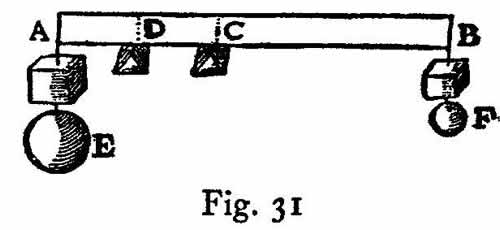
Hence it follows that the sum of the forces A and B bears to the sum of the forces E and F a ratio which is the product of the three following ratios, namely, BA/CA, BD/BC, and AD/AB. But DA/CA is the product of DA/BA and BA/CA. Therefore the sum of the forces A and B bears to the sum of the forces E and F a ratio which is the product of DA:CA and DB:CB. But the rectangle AD.DB bears to the rectangle AC.CB a ratio which is the product of DA/CA and DB/CB. Accordingly the sum of the forces A and B is to the sum of the forces E and F as the rectangle AD.DB is to the rectangle AC.CB, that is, the resistance to fracture at C is to the resistance to fracture at D as the rectangle AD.DB is to the rectangle AC.CB.
q. e. d.
Another rather interesting problem may be solved as a consequence of this theorem, namely,
Given the maximum weight which a cylinder or prism can support at its middle-point where the resistance is a minimum, and given also a larger weight, find that point in the cylinder for which this larger weight is the maximum load that can be supported.
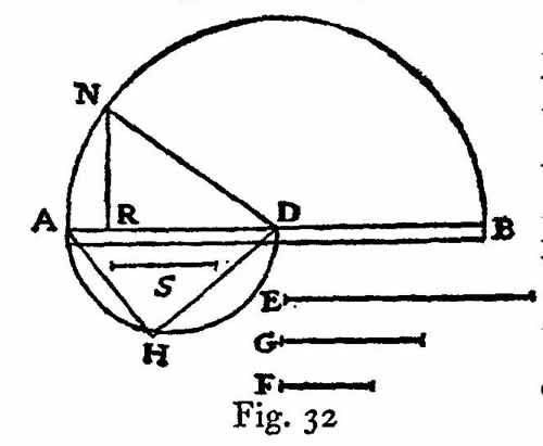
Let that one of the given weights which is larger than the maximum weight supported at the middle of the cylinder AB bear to this maximum weight the same ratio which the length E bears to the length F. The problem is to find that point in the cylinder at which this larger weight becomes the maximum that can be supported. Let G be a mean proportional between the lengths E and F. Draw AD and S so that they bear to each other the same ratio as E to G; accordingly S will be less than AD.
Let AD be the diameter of a semicircle AHD, in which take AH equal to S; join the points H and D and lay off DR equal to HD. Then, I say, R is the point sought, namely, the point at which the given weight, greater than the maximum supported at the middle of the cylinder D, would become the maximum load.
On AB as diameter draw the semicircle ANB: erect the perpendicular RN and join the points N and D. Now since the sum of the squares on NR and RD is equal to the square of ND, that is, to the square of AD, or to the sum of the squares of AH and HD; and, since the square of HD is equal to the square of DR, it follows that the square of NR, that is, the rectangle AR.RB, is equal to the square of AH, also therefore to the square of S; but the square of S is to the square of AD as the length F is to the length E, that is, as the maximum weight supported at D is to the larger of the two given weights. Hence the latter will be the maximum load which can be carried at the point R; which is the solution sought.
Now I understand thoroughly; and I am thinking that, since the prism AB grows constantly stronger and more resistant to the pressure of its load at points which are more and more removed from the middle, we could in the case of large heavy beams cut away a considerable portion near the ends which would notably lessen the weight, and which, in the beam work of large rooms, would prove to be of great utility and convenience.
It would be a fine thing if one could discover the proper shape to give a solid in order to make it equally resistant at every point, in which case a load placed at the middle would not produce fracture more easily than if placed at any other point.
I was just on the point of mentioning an interesting and remarkable fact connected with this very question. My meaning will be clearer if I draw a figure. Let DB represent a prism; then, as we have already shown, its resistance to fracture [bending strength] at the end AD, owing to a load placed at the end B, will be less than the resistance at CI in the ratio of the length CB to AB. Now imagine this same prism to be cut through diagonally along the line FB so that the opposite faces will be triangular; the side facing us will be FAB. Such a solid will have properties different from those of the prism; for, if the load remain at B, the resistance against fracture [bending strength] at C will be less than that at A in the ratio of the length CB to the length AB. This is easily proved: for if CNO represents a cross-section parallel to AFD, then the length FA bears to the length CN, in the triangle FAB, the same ratio which the length AB bears to the length CB. Therefore, if we imagine A and C to be the points at which the fulcrum is placed, the lever arms in the two cases BA, AF and BC, CN will be proportional [simili]. Hence the moment of any force applied at B and acting through the arm BA, against a resistance placed at a distance AF will be equal to that of the same force at B acting through the arm BC against the same resistance located at a distance CN. But now, if the force still be applied at B, the resistance to be overcome when the fulcrum is at C, acting through the arm CN, is less than the resistance with the fulcrum at A in the same proportion as the rectangular cross-section CO is less than the rectangular cross-section AD, that is, as the length CN is less than AF, or CB than BA.
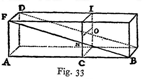
Consequently the resistance to fracture at C, offered by the portion OBC, is less than the resistance to fracture at A, offered by the entire block DAB, in the same proportion as the length CB is smaller than the length AB.
By this diagonal saw-cut we have now removed from the beam, or prism DB, a portion, i. e., a half, and have left the wedge, or triangular prism, FBA. We thus have two solids possessing opposite properties; one body grows stronger as it is shortened while the other grows weaker. This being so it would seem not merely reasonable, but inevitable, that there exists a line of section such that, when the superfluous material has been removed, there will remain a solid of such figure that it will offer the same resistance [strength] at all points.
Evidently one must, in passing from greater to less, encounter equality.
But now the question is what path the saw should follow in making the cut.
It seems to me that this ought not to be a difficult task: for if by sawing the prism along the diagonal line and removing half of the material, the remainder acquires a property just the opposite to that of the entire prism, so that at every point where the latter gains strength the former becomes weaker, then it seems to me that by taking a middle path, i. e., by removing half the former half, or one-quarter of the whole, the strength of the remaining figure will be constant at all those points where, in the two previous figures, the gain in one was equal to the loss in the other.
You have missed the mark, Simplicio. For, as I shall presently show you, the amount which you can remove from the prism without weakening it is not a quarter but a third. It now remains, as suggested by Sagredo, to discover the path along which the saw must travel: this, as I shall prove, must be a parabola. But it is first necessary to demonstrate the following lemma:
If the fulcrums are so placed under two levers or balances that the arms through which the forces act are to each other in the same ratio as the squares of the arms through which the resistances act, and if these resistances are to each other in the same ratio as the arms through which they act, then the forces will be equal.
Let AB and CD represent two levers whose lengths are divided by their fulcrums in such a way as to make the distance EB bear to the distance FD a ratio which is equal to the square of the ratio between the distances EA and FC. Let the resistances located at A and C be to each other as EA is to FC. Then, I say, the forces which must be applied at B and D in order to hold in equilibrium the resistances at A and C are equal. Let EG be a mean proportional between EB and FD. Then we shall have BE:EG=EG:FD=AE:CF. But this last ratio is precisely that which we have assumed to exist between the resistances at A and C. And since EG:FD=AE:CF, it follows, permutando, that EG:AE=FD:CF. Seeing that the distances DC and GA are divided in the same ratio by the points F and E, it follows that the same force which, when applied at D, will equilibrate the resistance at C, would if applied at G equilibrate at A a resistance equal to that found at C.
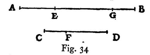
But one datum of the problem is that the resistance at A is to the resistance at C as the distance AE is to the distance CF, or as BE is to EG. Therefore the force applied at G, or rather at D, will, when applied at B, just balance the resistance located at A.
q. e. d.
This being clear draw the parabola FNB in the face FB of the prism DB. Let the prism be sawed along this parabola whose vertex is at B. The portion of the solid which remains will be included between the base AD, the rectangular plane AG, the straight line BG and the surface DGBF, whose curvature is identical with that of the parabola FNB. This solid will have, I say, the same strength at every point. Let the solid be cut by a plane CO parallel to the plane AD. Imagine the points A and C to be the fulcrums of two levers of which one will have the arms BA and AF; the other BC and CN. Then since in the parabola FBA, we have BA:BC=AFmacronsup2: CNmacronsup2, it is clear that the arm BA of one lever is to the arm BC of the other lever as the square of the arm AF is to the square of the other arm CN. Since the resistance to be balanced by the lever BA is to the resistance to be balanced by the lever BC in the same ratio as the rectangle DA is to the rectangle OC, that is as the length AF is to the length CN, which two lengths are the other arms of the levers, it follows, by the lemma just demonstrated, that the same force which, when applied at BG will equilibrate the resistance at DA, will also balance the resistance at CO. The same is true for any other section. Therefore this parabolic solid is equally strong throughout.
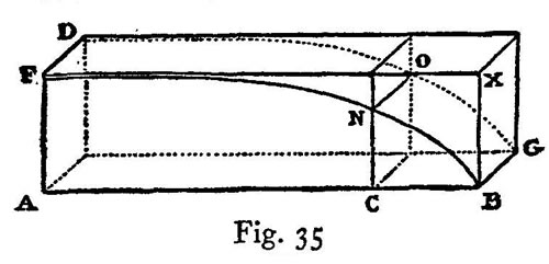
It can now be shown that, if the prism be sawed along the line of the parabola FNB, one-third part of it will be removed; because the rectangle FB and the surface FNBA bounded by the parabola are the bases of two solids included between two parallel planes, i. e., between the rectangles FB and DG; consequently the volumes of these two solids bear to each other the same ratio as their bases. But the area of the rectangle is one and a half times as large as the area FNBA under the parabola; hence by cutting the prism along the parabola we remove one-third of the volume. It is thus seen how one can diminish the weight of a beam by as much as thirty-three per cent without diminishing its strength; a fact of no small utility in the construction of large vessels, and especially in supporting the decks, since in such structures lightness is of prime importance.
The advantages derived from this fact are so numerous that it would be both wearisome and impossible to mention them all; but leaving this matter to one side, I should like to learn just how it happens that diminution of weight is possible in the ratio above stated. I can readily understand that, when a section is made along the diagonal, one-half the weight is removed; but, as for the parabolic section removing one-third of the prism, this I can only accept on the word of Salviati who is always reliable; however I prefer first-hand knowledge to the word of another.
You would like then a demonstration of the fact that the excess of the volume of a prism over the volume of what we have called the parabolic solid is one-third of the entire prism. This I have already given you on a previous occasion; however I shall now try to recall the demonstration in which I remember having used a certain lemma from Archimedes’ book On Spirals, namely, Given any number of lines, differing in length one from another by a common difference which is equal to the shortest of these lines; and given also an equal number of lines each of which has the same length as the longest of the first-mentioned series; then the sum of the squares of the lines of this second group will be less than three times the sum of the squares of the lines in the first group. But the sum of the squares of the second group will be greater than three times the sum of the squares of all excepting the longest of the first group.
Assuming this, inscribe in the rectangle ACBP the parabola AB. We have now to prove that the mixed triangle BAP whose sides are BP and PA, and whose base is the parabola BA, is a third part of the entire rectangle CP. If this is not true it will be either greater or less than a third. Suppose it to be less by an area which is represented by X. By drawing lines parallel to the sides BP and CA, we can divide the rectangle CP into equal parts; and if the process be continued we shall finally reach a division into parts so small that each of them will be smaller than the area X; let the rectangle OB represent one of these parts and, through the points where the other parallels cut the parabola, draw lines parallel to AP. Let us now describe about our “mixed triangle” a figure made up of rectangles such as BO, IN, HM, FL, EK, and GA; this figure will also be less than a third part of the rectangle CP because the excess of this figure above the area of the “mixed triangle” is much smaller than the rectangle BO which we have already made smaller than X.
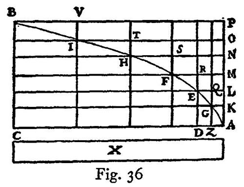
More slowly, please; for I do not see how the excess of this figure described about the “mixed triangle” is much smaller than the rectangle BO.
Does not the rectangle BO have an area which is equal to the sum of the areas of all the little rectangles through which the parabola passes? I mean the rectangles BI, IH, HF, FE, EG, and GA of which only a part lies outside the “mixed triangle.” Have we not taken the rectangle BO smaller than the area X? Therefore if, as our opponent might say, the triangle plus X is equal to a third part of this rectangle CP, the circumscribed figure, which adds to the triangle an area less than X, will still remain smaller than a third part of the rectangle, CP. But this cannot be, because this circumscribed figure is larger than a third of the area. Hence it is not true that our “mixed triangle” is less than a third of the rectangle.
You have cleared up my difficulty; but it still remains to be shown that the circumscribed figure is larger than a third part of the rectangle CP, a task which will not, I believe, prove so easy.
There is nothing very difficult about it. Since in the parabola DEmacronsup2:ZGmacronsup2=DA:AZ= rectangle KE: rectangle AG, seeing that the altitudes of these two rectangles, AK and KL, are equal, it follows that EDmacronsup2:ZGmacronsup2=LAmacronsup2:AKmacronsup2=rectangle KE: rectangle KZ. In precisely the same manner it may be shown that the other rectangles LF, MH, NI, OB, stand to one another in the same ratio as the squares of the lines MA, NA, OA, PA.
Let us now consider the circumscribed figure, composed of areas which bear to each other the same ratio as the squares of a series of lines whose common difference in length is equal to the shortest one in the series; note also that the rectangle CP is made up of an equal number of areas each equal to the largest and each equal to the rectangle OB. Consequently, according to the lemma of Archimedes, the circumscribed figure is larger than a third part of the rectangle CP; but it was also smaller, which is impossible. Hence the “mixed triangle” is not less than a third part of the rectangle CP.
Likewise, I say, it cannot be greater. For, let us suppose that it is greater than a third part of the rectangle CP and let the area X represent the excess of the triangle over the third part of the rectangle CP; subdivide the rectangle into equal rectangles and continue the process until one of these subdivisions is smaller than the area X. Let BO represent such a rectangle smaller than X. Using the above figure, we have in the “mixed triangle” an inscribed figure, made up of the rectangles VO, TN, SM, RL, and QK, which will not be less than a third part of the large rectangle CP.
For the “mixed triangle” exceeds the inscribed figure by a quantity less than that by which it exceeds the third part of the rectangle CP; to see that this is true we have only to remember that the excess of the triangle over the third part of the rectangle CP is equal to the area X, which is less than the rectangle BO, which in turn is much less than the excess of the triangle over the inscribed figure. For the rectangle BO is made up of the small rectangles AG, GE, EF, FH, HI, and IB; and the excess of the triangle over the inscribed figure is less than half the sum of these little rectangles. Thus since the triangle exceeds the third part of the rectangle CP by an amount X, which is more than that by which it exceeds the inscribed figure, the latter will also exceed the third part of the rectangle, CP. But, by the lemma which we have assumed, it is smaller. For the rectangle CP, being the sum of the largest rectangles, bears to the component rectangles of the inscribed figure the same ratio which the sum of all the squares of the lines equal to the longest bears to the squares of the lines which have a common difference, after the square of the longest has been subtracted.
Therefore, as in the case of squares, the sum total of the largest rectangles, i. e., the rectangle CP, is greater than three times the sum total of those having a common difference minus the largest; but these last make up the inscribed figure. Hence the “mixed triangle” is neither greater nor less than the third part of rectangle CP; it is therefore equal to it.
A fine, clever demonstration; and all the more so because it gives us the quadrature of the parabola, proving it to be four-thirds of the inscribed triangle, a fact which Archimedes demonstrates by means of two different, but admirable, series of many propositions. This same theorem has also been recently established by Luca Valerio, the Archimedes of our age; his demonstration is to be found in his book dealing with the centers of gravity of solids.
A book which, indeed, is not to be placed second to any produced by the most eminent geometers either of the present or of the past; a book which, as soon as it fell into the hands of our Academician, led him to abandon his own researches along these lines; for he saw how happily everything had been treated and demonstrated by Valerio.
When I was informed of this event by the Academician himself, I begged of him to show the demonstrations which he had discovered before seeing Valerio’s book; but in this I did not succeed.
I have a copy of them and will show them to you; for you will enjoy the diversity of method employed by these two authors in reaching and proving the same conclusions; you will also find that some of these conclusions are explained in different ways, although both are in fact equally correct.
I shall be much pleased to see them and will consider it a great favor if you will bring them to our regular meeting. But in the meantime, considering the strength of a solid formed from a prism by means of a parabolic section, would it not, in view of the fact that this result promises to be both interesting and useful in many mechanical operations, be a fine thing if you were to give some quick and easy rule by which a mechanician might draw a parabola upon a plane surface?
There are many ways of tracing these curves; I will mention merely the two which are the quickest of all. One of these is really remarkable; because by it I can trace thirty or forty parabolic curves with no less neatness and precision, and in a shorter time than another man can, by the aid of a compass, neatly draw four or six circles of different sizes upon paper. I take a perfectly round brass ball about the size of a walnut and project it along the surface of a metallic mirror held in a nearly upright position, so that the ball in its motion will press slightly upon the mirror and trace out a fine sharp parabolic line; this parabola will grow longer and narrower as the angle of elevation increases. The above experiment furnishes clear and tangible evidence that the path of a projectile is a parabola; a fact first observed by our friend and demonstrated by him in his book on motion which we shall take up at our next meeting. In the execution of this method, it is advisable to slightly heat and moisten the ball by rolling in the hand in order that its trace upon the mirror may be more distinct.
The other method of drawing the desired curve upon the face of the prism is the following: Drive two nails into a wall at a convenient height and at the same level; make the distance between these nails twice the width of the rectangle upon which it is desired to trace the semiparabola. Over these two nails hang a light chain of such a length that the depth of its sag is equal to the length of the prism. This chain will assume the form of a parabola, so that if this form be marked by points on the wall we shall have described a complete parabola which can be divided into two equal parts by drawing a vertical line through a point midway between the two nails. The transfer of this curve to the two opposing faces of the prism is a matter of no difficulty; any ordinary mechanic will know how to do it.
By use of the geometrical lines drawn upon our friend’s compass, one may easily lay off those points which will locate this same curve upon the same face of the prism.
Hitherto we have demonstrated numerous conclusions pertaining to the resistance which solids offer to fracture. As a starting point for this science, we assumed that the resistance offered by the solid to a straight-away pull was known; from this base one might proceed to the discovery of many other results and their demonstrations; of these results the number to be found in nature is infinite. But, in order to bring our daily conference to an end, I wish to discuss the strength of hollow solids, which are employed in art—and still oftener in nature—in a thousand operations for the purpose of greatly increasing strength without adding to weight; examples of these are seen in the bones of birds and in many kinds of reeds which are light and highly resistant both to bending and breaking. For if a stem of straw which carries a head of wheat heavier than the entire stalk were made up of the same amount of material in solid form it would offer less resistance to bending and breaking. This is an experience which has been verified and confirmed in practice where it is found that a hollow lance or a tube of wood or metal is much stronger than would be a solid one of the same length and weight, one which would necessarily be thinner; men have discovered, therefore, that in order to make lances strong as well as light they must make them hollow. We shall now show that:
In the case of two cylinders, one hollow the other solid but having equal volumes and equal lengths, their resistances [bending strengths] are to each other in the ratio of their diameters.
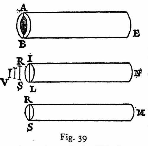
Let AE denote a hollow cylinder and IN a solid one of the same weight and length; then, I say, that the resistance against fracture exhibited by the tube AE bears to that of the solid cylinder IN the same ratio as the diameter AB to the diameter IL. This is very evident; for since the tube and the solid cylinder IN have the same volume and length, the area of the circular base IL will be equal to that of the annulus AB which is the base of the tube AE. (By annulus is here meant the area which lies between two concentric circles of different radii.) Hence their resistances to a straight-away pull are equal; but in producing fracture by a transverse pull we employ, in the case of the cylinder IN, the length LN as one lever arm, the point L as a fulcrum, and the diameter LI, or its half, as the opposing lever arm: while in the case of the tube, the length BE which plays the part of the first lever arm is equal to LN, the opposing lever arm beyond the fulcrum, B, is the diameter AB, or its half. Manifestly then the resistance [bending strength] of the tube exceeds that of the solid cylinder in the proportion in which the diameter AB exceeds the diameter IL which is the desired result. Thus the strength of a hollow tube exceeds that of a solid cylinder in the ratio of their diameters whenever the two are made of the same material and have the same weight and length.
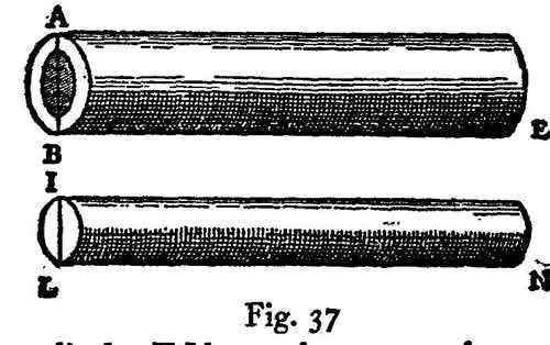
It may be well next to investigate the general case of tubes and solid cylinders of constant length, but with the weight and the hollow portion variable. First we shall show that:
Given a hollow tube, a solid cylinder may be determined which will be equal [eguale] to it.
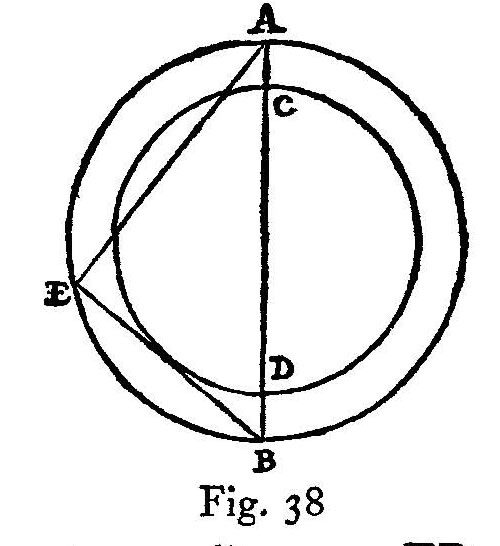
The method is very simple. Let AB denote the external and CD the internal diameter of the tube. In the larger circle lay off the line AE equal in length to the diameter CD; join the points E and B. Now since the angle at E inscribed in a semicircle, AEB, is a right-angle, the area of the circle whose diameter is AB is equal to the sum of the areas of the two circles whose respective diameters are AE and EB. But AE is the diameter of the hollow portion of the tube. Therefore the area of the circle whose diameter is EB is the same as the area of the annulus ACBD. Hence a solid cylinder of circular base having a diameter EB will have the same volume as the walls of the tube of equal length.
By use of this theorem, it is easy:
To find the ratio between the resistance [bending strength] of any tube and that of any cylinder of equal length.
Let ABE denote a tube and RSM a cylinder of equal length: it is required to find the ratio between their resistances. Using the preceding proposition, determine a cylinder ILN which shall have the same volume and length as the tube. Draw a line V of such a length that it will be related to IL and RS (diameters of the bases of the cylinders IN and RM), as follows: V:RS=RS:IL. Then, I say, the resistance of the tube AE is to that of the cylinder RM as the length of the line AB is to the length V. For, since the tube AE is equal both in volume and length, to the cylinder IN, the resistance of the tube will bear to the resistance of the cylinder the same ratio as the line AB to IL; but the resistance of the cylinder IN is to that of the cylinder RM as the cube of IL is to the cube of RS, that is, as the length IL is to length V: therefore, ex æquali, the resistance [bending strength] of the tube AE bears to the resistance of the cylinder RM the same ratio as the length AB to V.
q. e. d.